Outside of civilian and military aircraft propulsion, one hears little about gas turbines as “prime movers”. In terms of propulsion on land and sea, existing examples are almost exclusively military: navy ships and main battle tanks – primarily, the M1 Abrams in the USA and T-80 in Russia. A notable exception is the application of GE Vernova’s LM series aeroderivatives in large cruise ships.
Things were not always like this. Between early 1950s and 1970s, gas turbine engine development was actively pursued on both sides of the Atlantic for applications in land-based vehicle propulsion – both military and civilian. This article provides a brief look into a relatively obscure chapter in the history of gas turbines.
A prophesy was made in a book first published in Germany in 1916, i.e., during WWI: gas turbine engines (burning fuel oil) were deemed favorable (vis-à-vis steam turbines) as prime movers for torpedoes, aircraft and large ships.
The authors even envisioned a gas turbine as a driver for mobile “large guns” – self-propelled large caliber mortar. Keep in mind that this was 15-20 years before Hans von Ohain and Sir Frank Whittle tinkered with primitive “jet engines” in their respective garages.
Turbojet vs. turboshaft and gas turbine locomotives
There are two ways to use a gas turbine for propulsion: as a turbojet (generating thrust) or as a shaft drive (turning a wheel or propeller). The first is obviously the primary means of propulsion for large military and civilian aircraft. But there are also many examples of turboshaft engines driving aircraft propellers, or rotors in helicopters.
Strangely enough, turbojet aircraft engines were investigated for railroad applications in 1960s. In the USA, two GE J47-19 jet engines (designed for the Convair B-36 “Peacemaker” bomber) were mounted on the roof of a diesel railroad locomotive. In 1966, the train was tested on an “arrow-straight” track, reaching a speed of about 296 km/h (184mph).
In 1970, Soviets tried the same with two turbojets from a Yakovlev Yak-40 airliner mounted on the roof of the locomotive (Figure 1). It was tested in 1971 and reportedly got up to 413 km/h (256 mph).

Ultimately, high fuel consumption, deafening noise of the turbojets (imagine one of those pulling into a railway station) and the need for straight tracks to prevent derailing at such high speeds forced these attempts to be dropped once and for all.
The second (and more practical propulsion option) was a turboshaft application, first tried back in the 1930s. The configuration was identical to a modern diesel-electric locomotive with the gas turbine replacing the diesel engine as the shaft drive.
The first one was the 550-hp Götaverken turbo-compound engine with a diesel engine hot gas generator on a Nydquist & Holm locomotive in Sweden in 1933. The next and better-known example was Swiss Federal Railways Am 4/6 powered by a Brown Boveri Cie. (BBC) 2,200 hp gas turbine, ordered in 1939 – the same year when BBC’s 4 MW Neuchâtel gas turbine electric power plant was commissioned. Trials started in 1941, but they were ceased due to wartime fuel shortage. (Its fuel efficiency was a not-so-great 18.4% at 1,700 hp output.)
British, US, French, and Russian attempts were all post-WWII. In the US, the Union Pacific Railroad used gas turbine-electric drive locomotives (GTEL) until the end of 1960s. The third generation GTEL with GE’s Frame 5 gas turbine burning Bunker C fuel, rated at 8,500 hp, was the most powerful in the world by a large margin.
Early automotive applications
As for the automotive propulsion applications, American carmakers’ full-blown R&D efforts to deploy gas turbine engines in trucks and passenger vehicles can be traced back to early 1950s. However, the idea or concept of automotive gas turbine engines for automostive propulsion was investigated before WWII.
In the 1930s, Chrysler Corporation conducted an engineering study to explore the possibility of turning the idea into a final product. But materials and manufacturing techniques were deemed too costly, in terms of money and time, to develop a commercially viable power plant for cars.
Germany in WWII (1944-45) and the turbopanzer
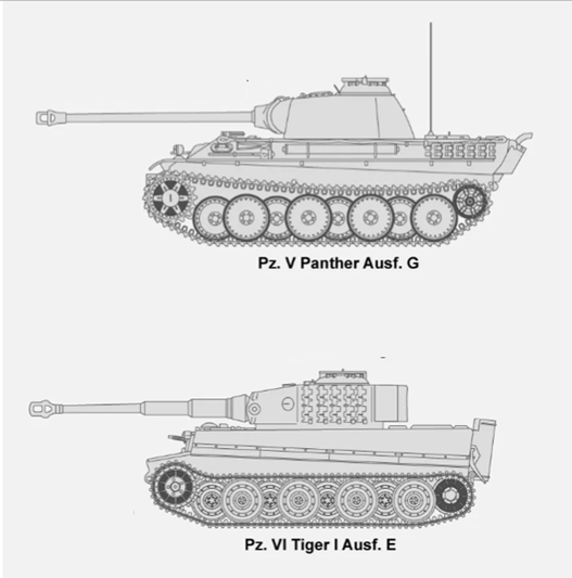
In July 1944, the SS leadership issued an order to start the development of gas turbine engines for the Panther and Tiger tanks (the “Big Cats”, Figure 2 ) capable of burning “low value” liquid fuels.
At that time, German heavy tanks were powered exclusively by Maybach gasoline engines. The objective of the gas turbine retrofit was to conserve “high value” fuels such as high-octane aviation gasoline, which Germany had extreme difficulty in producing in sufficient quantities.
In a report dated February 1, 1945 (only four months before Germany’s surrender) the research group (code named Alfred) stated that aircraft jet engines mounted on the vehicle were unsuitable for propulsion. (This might have worked both as a propulsion unit and a flame thrower in reverse – the problem would be how to maneuver.)
The obvious solution was to use the gas turbine exhaust gas to drive another (power) turbine, producing shaft work, i.e., a turboshaft arrangement. Two alternative configurations were to be considered, as illustrated in Figure 3, Types A and B, without and with a “regenerator” (thermodynamically similar to a “recuperator”).
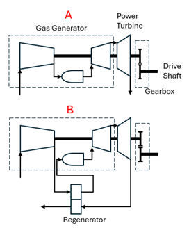
Recognizing the low fuel efficiency of the gas turbine engine, engineers proposed regeneration to make use of the still hot exhaust gas to pre-heat the combustion air and reduce the fuel burn. However, this option was rejected to save cost and space, albeit at the expense of fuel efficiency.
The work begins
The team began its work late August 1944 and followed two design paths. The first path involved a pure gas turbine to be designed in a month’s time and then constructed by the Waffen-SS group (employing slave labor supplied by the nearby Mauthausen concentration camp).
For the combustion chamber, various proposals were considered, including a “nozzleless” rotating burner scheme (i.e., a quasi-Nernst turbine). The compressor was to be axial or diagonal axial, based on a unique Heinkel-Hirth design by Hans von Ohain for the HeS-011 jet engine, which was already available.
The second idea involved inclusion of a steam turbine, to be connected to the gas turbine, resulting in a “combined cycle” engine. To improve the gas turbine performance, and due to the severely limited availability of alloy materials in Germany, the R&D work also included novel blade cooling designs and the use of ceramic turbine blades; the latter ultimately being discarded due to the significant development effort needed to realize it.
The final design selection was planned to take place in December 1944, with the first steam-gas combined cycle power plant prototype to be ready by May 1, 1945. However, this somewhat bizarre idea was apparently dropped rather quickly since the January 1945 report is silent on it.
Special propulsion requirements for tanks
A tank engine imposed several requirements on basic gas turbine propulsion, which could not be met by a simple repurposing of aircraft jet engines available at the time, namely the need to achieve (1) a wider operating speed envelope; (2) reasonable fuel consumption at part load; (3) slowing the power turbine under no-load conditions; and (4) adaptation of the torque curve to the wide operating speed range to minimize the number of reduction gears.
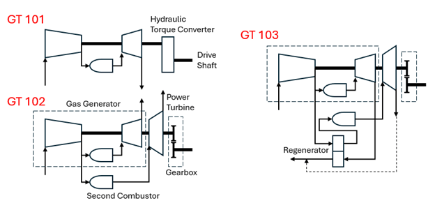
With those requirements in mind, the development team, led by Dr. Alfred Müller, came up with five potential engine architectures, including the two basic configurations shown in Figure 3, and three more (see Figure 4), two of which, GT 101 (a direct drive through a hydraulic torque converter) and GT 102 (with a fired power turbine), were examined by the team for the experimental tank.
It is noted that, according to testimony after the war, Dr. Müller said that he had first proposed the gas turbine engine as the most suitable to tank applications in 1943 but could not interest the military authorities.
His reasons to favor gas turbines for propulsion included lighter weight and lower cost (vis-à-vis piston-cylinder engines, especially with high turbine inlet temperatures), ability to use low grade fuels, simpler transmission, and no complex water-cooling circuit.
To these he added the absence of vibration and simpler air filtration. However, as later field experience of the US Army’s M1 Abrams tank in the Iraqi desert showed, the last one (air filtration) was actually not true.
As a side note to history, it should be mentioned here that Dr. Ferdinand Porsche and his team, including Karl Rabe and Otto Zadnik, had come up with their own 1,000-hp gas turbine engine design, under the code name Typ 305, which was identical to the GT 102 configuration in Figure 4. However, by mid-1944, Himmler’s SS took over the lead of this initiative and handed it to Dr. Müller and his team.
So, most likely, Müller’s GT 102 configuration was inspired by Porsche’s Typ 305 design, and the addition of a regenerator in GT 103 was apparently the idea of Otto Zadnik, Dr. Porsche’s right-hand man.
From a torque-speed characteristic perspective, the GT 102 (with a separate fired power turbine) is advantageous with high torque at stall (see Figure 5). However, it was not favored by the designers because of the difficulties associated with meeting the third requirement above (limiting no-load turbine speed) and cost considerations (e.g., its six bearings).

Note that a free power turbine rotating at an already high 20,000 rpm will spin out of control and destroy the blades and casing if the load is removed. This can be prevented either by mechanical braking or diverting the hot gas coming from the gas generator (still spinning at 14,000 rpm)
First viable alternative
Thus, GT 101, a simple gas turbine (no power turbine) powering the output drive shaft through a hydraulic torque converter, was deemed to be the first viable propulsion alternative. The ideal implementation of it would be through an electric motor drive, as favored by Dr. Porsche (as implemented in his original Tiger design and saw action as Ferdinand (Elefant) tank destroyer during the war with Maybach HL120 TRM engines) but copper shortages in Germany precluded this option.
To accommodate the unfavorable torque-speed behavior of GT 101, a complex gearbox would be necessary for power transmission. (A considered alternative was a hydraulic torque converter, as shown in Figure 4, e.g., of a Thoma hydrostatic or Föttinger hydrodynamic type.)
The original combustor scheme involved rotating fuel burners (no nozzles) to prevent hot spots on the turbine inlet stator vanes (clearly inspired by the Nernst cycle). The conventional option, an annular combustor with 14 fixed fuel burners, was kept in a back pocket in case the rotating scheme could not be implemented within the tight development schedule (it was not!).
The engine schematic drawing and the concept for installation in the vehicle is shown in Figure 6. The original compressor was of the Heinkel-Hirth jet engine type with two diagonal and four axial stages. A substitute design with nine axial stages was also planned as depicted in installation sketches from recovered design documents.

A rather complicated hydraulic transmission system had to transfer the shaft power from the cold end of the turbine engine mounted in the rear to the drive wheels in front of the vehicle. Dr. Otto Zadnik of Dr. Porsche’s team was responsible for the transmission design and installation of the engine inside the tank.
Fuel and air consumption issues
The key consideration for the project team was the ability of the gas turbine to use low grade fuels. Within the existing limits of manufacturing technology and materials, specific fuel consumption was estimated as 450 g/hp-hr for the 1,000 hp gas turbine engine (or only about 14% net efficiency), which was significantly higher than the state-of-the-art with gasoline engines, 250-300 g/hp-h, under road conditions.
Even when using less expensive low-grade fuel, the implication of the extra fuel tank capacity to maintain the tank’s operating range vis-à-vis the 690 hp Maybach gasoline engines, was a serious issue.
Another constraint was the opening in the hull, which must be small yet allow the intake of engine airflow. Dr. Müller estimated air consumption for gasoline engines at 6 kg/s (1 kg/s cylinder intake, 5 kg/s radiator cooling air) for 1,000 hp output vis-à-vis 10 kg/s for the gas turbine engine with 800°C turbine inlet temperature (TIT).
The desired reduction in airflow and specific fuel consumption required higher TIT, e.g., 1,000°C, uncooled blades, and a regenerator (gas-to-air heat exchanger).
Table 1 summarizes calculations performed by the author in THERMOFLEX, which confirm Dr. Müller’s estimates for GT 101. Note that the third column shows the positive impact of adding regeneration to GT 101, effectively halving the specific fuel consumption (>2x the net efficiency).
Table 1 GT 101 THERMOFLEX model calculations
| Airflow, kg/s | 10 | 5.5 | 5.5 |
| TIT, C | 800 | 1000 | 1000 |
| Compressor PR | 4.5:1 | 4.5:1 | 4.5:1 |
| Regeneration | N | N | Y |
| Blade Cooling | Y | N | N |
| Turbine Shaft, kW | 2829 | 1991 | 1964 |
| Compressor Shaft, kW | 1854 | 1020 | 1054 |
| Net Shaft, kW | 975 | 971 | 909 |
| Net Horsepower | 1177 | 1172 | 1098 |
| Fuel Burn, kWth | 6351 | 5269 | 2363 |
| Fuel Flow, kg/s | 0.1461 | 0.1212 | 0.0544 |
| Net Efficiency | 13.8% | 16.6% | 34.7% |
| Fuel Consumption, g/hp-h | 447 | 372 | 178 |
Has a gas turbine ever powered a German Panzer?
The answer is (or must be) a definite no. Interestingly, however, Ferdinand Piëch, Dr. Ferdinand Porsche’s grandson, told a biographer a gas turbine equipped Jagdtiger was tested in Austria.
According to Herr Piëch, Dr. Müller’s turbine engine was fitted into the tank, “placed high and longitudinally at the rear, it drove forward and down through reduction gears to the transmission.” He also mentioned that “650°C exhaust gas vented upwards and burned up the trees around the tank!”
However, such an installation and field test are otherwise undocumented. As it turns out a turbine engine was not the only new prime mover the Germans were in search of to replace the problematic Maybach HL230 engine used in their heavy tanks, the Panther and the Tiger (the “big cats” of Figure 2).
Meanwhile, the vehicle selected for the first trial run of a new engine was the Jagdtiger, and it was already dedicated to experimental work by Dr. Porsche, who was working with Simmering Graz Pauker A.G. on a new 800 hp turbocharged 16-cylinder diesel engine, known as Simmering Sla 16.
The Sla 16-powered Jagdtiger reportedly went on a few test drives. Allied reports compiled after the war state that the tests were satisfactory and the new diesel engine outperforming the Maybach in every respect. In March 1945, it was decided to put the engine into production. When the war ended, the vehicle, engines and drawings fell into the hands of the advancing Soviet army.
So, what did Herr Piëch actually see?
In his commentary, Herr Piëch probably was referring to one of those Sla-16 powered Jagdtiger test drives. That he saw flames coming out of the exhaust pipes was normal for an internal combustion engine, especially for a turbocharged diesel. The culprit is unburnt fuel in the exhaust gas stream igniting in the hot exhaust pipe. (It is also a common phenomenon in badly tuned gasoline car engines, commonly known as “backfire”.)
Memoirs of a German Panther tank driver mention being able to follow the tank ahead (another Panther) at night in a dense forest by focusing on the flames coming from its exhaust. (This was during the desperate escape of scattered German forces from the advancing Red Army in 1945 – normally, the panzers did not operate at night.)
End of the story?
The bottom line is that neither GT 101 nor 102 was built and installed in an experimental tank. In interviews with British interrogators after the war, Dr. Müller and Paul Kolb (of BMW) stated that by the end of the war (for Germany) in May 1945, the gas generator design (basically, the GT 101) was complete, and manufacturing had started in Mittelwerken GmbH, where V2 rockets were assembled.
The compressor test stand was relocated from BBC Mannheim to Mittelwerk with tests scheduled to start in February 1945. Completion of GT 101 was scheduled for June, and GT 102 with the power turbine, for the end of July, the latest.
Related reading: “Decarbonizatiion and the lessons from land based propulsion.”
The installation of the complete unit in the test tank was planned to take place under the supervision of Dr. Porsche and Herr Zadnik. Records show that in Easter of 1945 parts arrived. However, the front was coming near, and the parts were shipped back. A nearby work camp inmate (moved from the Mauthausen for the turbopanzer project) reported that no experiments with tank engines were undertaken.
Post-war developments
While the German efforts to manufacture a Turbopanzer came to naught, their efforts did not go to waste. The British were rather interested in their work and, right after the war, Dr. Müller and some of his team members ended up in C.A. Parsons & Co. in Newcastle-on-Tyne, England, to work on gas turbine engines for military vehicle propulsion (according to Ludvigsen, so did Otto Zadnik). Waldemar Hryniszak (the regenerator expert from BBC, Mannheim) was one of them and, apparently, he stayed on as part of a team under Dr. T. A. Bowden studying turbine engines and publishing on them (including a monograph).
Eventually, two gas turbine engine drives were built. One, rated at 650 hp, was installed and tested in a Conqueror heavy tank. The second one was rated at 950 hp. But the project was eventually discontinued due to excessive fuel consumption.
Note that the test unit comprised a gas generator and power turbine without a regenerator (à la GT 102). Details of the engine and the trials can be found here
The late armor expert Ogorkiewicz reported that the Soviets started their tank gas turbine engine program in 1949. Although not explicitly mentioned, it is likely that they made use of captured German documents, equipment, and maybe even personnel (engineers and/or technicians).
The culmination of Soviet gas turbine engine development over the next 25 years (with many failed attempts and cancellations over that time) was GTD-1000, and later GTD-1250, deployed in T-80B and T-80U MBTs, respectively. Thus, T-80 became the first serial production MBT with gas turbine propulsion in 1976.
Soviet engines were rather straightforward in their design approach: a gas generator comprising two centrifugal compressors and an axial turbine, and a two-stage axial power turbine combined with a hydrostatic transmission. Regenerators were deemed unreliable by Soviet designers, who accepted the high fuel consumption (about twice that of the diesel engines), arguing that the reduction in engine volume opened up space for extra fuel storage.
Even before the Soviet GTD-1000 engine and T-80 MBT, there was the turretless Swedish S-Tank (Stridsvagn or Strv 103),with a dual diesel and gas turbine power plant in late 1950s. This was a unique design in all aspects. It was powered by a Rolls Royce opposed-piston K60 240-hp diesel engine (for slow speeds and aiming maneuvers) and a 490-hp Caterpillar 553 (formerly Boeing) gas turbine (for high speeds and rough terrain), originally developed for helicopters. The tank served in the Swedish armed forces until the 1990s.
AGT1500 powers the US M1 Abrams Tank
The most famous gas turbine tank engine is undoubtedly the Honeywell (formerly Avco then Textron Lycoming) AGT1500 powering the M1 Abrams MBT of the U.S. Armed Forces. And here is where the German connection reappears.
The Lycoming T53 turboshaft gas turbine was developed under the leadership of Dr. Anselm Franz, who had led the development of the Jumo-004 turbojet (the propulsion unit of the twin-engine Messerschmitt 262). Doctor Franz had first proposed his engine for application in a tank but that went nowhere, and it became the power plant of Bell UH-1, the “Huey”, the first turbine-powered helicopter in service.
In 1963 Dr. Franz and his team started the design of AGT1500 and its sister machine PLT27 (for helicopters). The regenerated engine had a cascaded, or twin-shaft, gas generator comprising HP and LP turbine-compressor trains and feeding the power turbine (see Figure 7).

It is rated at 1,500 hp at 3,000 rpm (3,754 Nmor 2,769 ft-lb of torque). Peak torque is 5,355 Nm (3,950 ft-lb) at 1,000 rpm. With a large recuperator at the exhaust end acting as a silencer, the AGT1500 engine is exceptionally quiet.
The engine was selected as the power plant for M1 in 1976 and entered mass production in 1979. The M1 Abrams tank powered by an AGT1500 first saw combat in the 1991 Gulf War. By 2008, over 12,000 units had been manufactured and installed in M1 tanks.
1960s Turbo cars and trucks
Gas turbine cars (and trucks) were seriously considered on both sides of the Atlantic during the years following WWII. Prototypes were built in the UK (Rover in 1950), Italy (Fiat Turbina in 1954), and the US (GM’s Firebird I in 1953) but none were considered and/or deemed feasible for serial production. In the U.S., GM, Ford, and Chrysler were active in developing gas turbine drives for trucks and automobiles. While Chrysler’s focus was on cars, GM and Ford aimed for applications to large trucks.
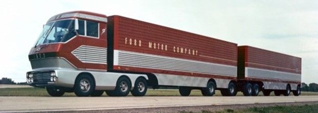
Ford’s experimental truck, the “Big Red” (Figure 8), was powered by Ford’s Model 705 gas turbine engine rated at 600 hp (at 3,080 rpm). A functional prototype (the only one ever built) was first shown to the public in 1964 during the 1964/65 World’s Fair in New York City.
One year after Big Red’s debut, GM’s Chevrolet division introduced the Turbo Titan III truck powered by the 280 hp (at 4,000 rpm) GT-309 gas turbine engine, also at the New York World’s Fair.
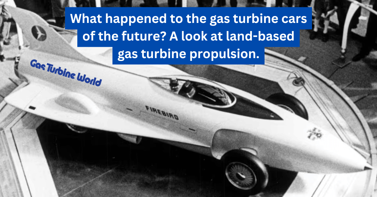
The GM engine was a culmination of R&D efforts going back to early 1950s; the GT-304 and GT-305 gas turbine engines were used in futuristic “Firebird” concept cars. (See main article image of a “Turbo Car”.) Ultimately, GM gave up on gas turbines in passenger cars about 10 years before Chrysler, and decided that application to larger vehicles was a better bet.
Both GM GT-309 and Ford Model 705 were textbook gas turbine engines (à la Type B, Figure 3) comprising a gas generator (they were called “gasifiers” by the OEMs), a regenerator, and an axial (LP) power turbine. A further improvement in the basic configuration is a multi-stage compressor with an intercooler, as implemented in the 705 (see below).
The gas generator was a “free shaft” comprising a radial compressor and an axial (HP) turbine with the combustion chamber in between. The regenerator served two purposes simultaneously, i.e., increasing thermal efficiency via combustion air pre-heating and cooling the exhaust gas to a level suitable for exhausting to the atmosphere. (It also acted as a muffler!)
The Ford 705: intercooled/recuperated with reheat
Although the Ford and GM engines were similar in basic configuration, both had their own unique characteristics.
The Ford engine Model 705 (see schematic Figure 9), rated at 600 hp, was an intercooled-recuperated gas turbine with reheat, i.e., a second combustor between the HP and LP turbines. It was originally developed for military applications such as tanks, mine sweepers, and small naval vessels under the aegis of the Army-Navy Gas Turbine Development Program. (Ford’s engine concept was one of the three selected by the Army-Navy Program; the other two were by Solar Turbines and the Canadian company Orenda.)

The two compressors and the HP turbine were of the radial type. The first, or LP, compressor (the “supercharger”), driven by an axial LP turbine, rotated at 36,600 rpm. The second, or HP, compressor, driven by the radial HP turbine, rotated at 75,500 rpm. Airflow is 4.5 lb/s with 214 psia at the HP turbine inlet (PR 14.5). HP turbine inlet temperature is 1,750°F (~955°C).
Despite its complex architecture and recuperation to maximize fuel efficiency, the result was not encouraging. Using a THERMOFLEX model of the engine, the author calculated about 28.5% net efficiency assuming a generous 90% polytropic efficiency for all the components.
The only redeeming value of the high-torque turbine engine was that it would be less expensive to run (using diesel or other fuels) and far quieter than any diesel engine.
Marketing hype about turbine trucks aside, Ford probably realized that the Big Red project was not viable for mass production due to the cost and efficiency problems that doomed turbine cars such as Chrysler’s Ghia (see below). Ford did not even have a use for the prototype after its cross-country promotional tour ended and the Big Red was left to rot in a hangar in North Carolina (sans Model 705 engine, which was probably destroyed by Ford).
The Chrysler Turbine Ghia
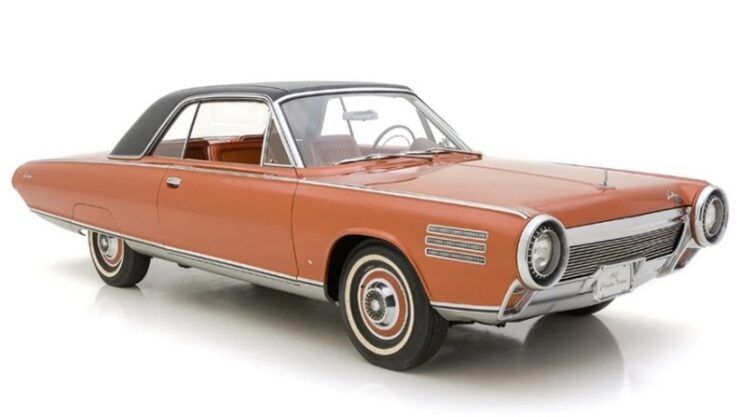
In the 1960s, around the same time Ford and GM were focused on a turbine truck engine, Chrysler’s Turbine Ghia (Figure 10), with the company’s fourth generation turbine engine, (Figure 11), came close to making it to the commercial scene. But, ultimately, plagued by excessive manufacturing costs, Chrysler executives could not pull the trigger.

Thermodynamically, the engine was also of Type B configuration (with regeneration) in Figure 3, featuring two rotating regenerators in vertical planes (one on each side) and a centrally located single-can, reverse flow combustor burning a wide variety of fuels, e.g., gasoline, diesel fuel, kerosene, JP-4, etc.
The four-stage radial compressor had a pressure ratio of 4:1. Power rating was 130 hp at 3,600 rpm output shaft speed with 425 lb-ft stalling torque (power turbine speed was 45,700 rpm, compressor turbine 44,600 rpm). Compressor and power turbines were single stage axial (the power turbine had variable stator vanes).
The Turbine Ghia’s extensive road test program with 50 cars given to selected drivers (from 30,000 applicants) for daily use across the country went well. At the end, however, in addition to manufacturing cost and complexity, poor fuel economy (percent efficiency in low 20s) and high NOx emissions (with soon to be enacted emissions regulations) spelled the doom for the turbine car.
Today, one of the nine surviving examples (out of 55 total produced) of this unique car is in American talk show host Jay Leno’s garage. Interested readers can watch him on YouTube driving his Turbine Ghia on California roads.
Concluding observations
Human ingenuity developing innovative solutions to existing and, in many cases non-existing, problems is an undeniable fact. Also undeniable is the human folly in insisting on infeasible and, sometimes, bizarre concepts in direct contradiction to hard-to-refute technical and economical facts.
One manifestation of this is the desire to invent “silver bullet” technologies to fight the insurmountable odds in an otherwise unwinnable battle. The German turbopanzer is one classic case in point.
Gas turbine power plants for cars and trucks (well below 1,000 hp) is an example of futilely insisting on an application of a technology knowing there is no chance of it replacing the existing technology with better efficiency, emissions, capex/opex, and performance (except for high “brake torque”).
In fact, the Russians already gave up on gas turbine engines in tanks. Diesel versions of T-80 are currently manufactured and used in several countries. Their next generation tank, T-14 Armata, is powered by a 1,500 hp diesel engine.
Similarly, the next generation U.S. M-1E3 tank, will reportedly be powered by a hybrid diesel-electric power plant, 50% more fuel-efficient than the current M1 Abrams.
Lesson learned: in the end, fundamental thermodynamics and aerodynamics dictate the barriers: superiority of constant volume combustion vis-à-vis constant pressure combustion, difficulty of achieving respectable component efficiencies at small blade/annulus sizes and high speeds, and the cost of manufacturing high temperature parts from exotic materials — all of which suggest gas turbines as “prime movers” in land propulsion will never become the standard.
For further reading on gas turbine engine development for German tanks during WWII, download this expanded version. CLICK HERE.
About the Author:
Dr. John Gülen, ASME Fellow, is an internationally-recognized expert in steam and gas turbine combined cycle systems and thermal power plant engineering, and has numerous patents and publications, including five monographs, to his credit. Dr. Gülen’s contributions include development of heat balance software at Thermoflow, Inc., design, optimization, and testing of combined cycle systems with FB and H class gas turbines at General Electric and technical assessment and studies of novel technologies for sustainable power generatioin at Bechtel. He was named a Bechtel Fellow in 2018. Dr. Gülen received his PhD degree in mechanical engineering from Rensselaer Polytechnic Institute and is a licensed professional engineer.