
FEED Study confirms exhaust gas recirculation reduces size and cost of carbon capture unit.
GE Vernova recently completed a 2-year front end engineering design (FEED) study, sponsored by the US DOE, of an integrated carbon capture retrofit at the natural gas-fired James M . Barry (2×1) GE 7F combined cycle power plant in Bucks, Alabama. The retrofit, applying Linde’s Gen 2 carbon capture solution based on BASF’s blue gas treatment technology, is capable of capturing up to 95% of the plant’s CO2 emissions.
The FEED analysis included installation of an exhaust gas recirculation (EGR) system which was evaluated to confirm expected technical and economic benefits with respect to plant design and performance:
Absorber towers. Reduced required cross sectional area of CO2 absorbers by almost 50%, halving the number of absorber towers required .
Plant emissions. Reduced overall plant emissions (NOx, PM, CO) by around 40% .
Energy savings. Reduced power penalty of carbon capture by around 7 .5MW by lowered process steam requirements.
Cost savings. More than 6% reduction in total cost of the carbon capture facility.
Pathways to decarbonized Natural Gas Combined Cycle Plants
Many government and power industry groups are seeking pathways to decarbonize or reduce carbon intensity of natural gas-fired power generation. The two main pathways for decarbonization of natural gas combined cycle (NGCC) plants are pre-combustion and post combustion carbon capture.
The choice for any particular NGCC plant depends on a number of different criteria, such as fuel price, space availability, capacity factor and availability of carbon dioxide (CO2) transport and storage infrastructure.
While pre-combustion capture deals with production of low-carbon or carbon-free alternative fuels (e .g ., hydrogen and ammonia), this article focuses on the post combustion carbon capture pathway.
More specifically, on impacts and benefits of applying EGR technology to reduce total flue gas flow to the carbon capture system. This is done by reintroducing some of the flue gas back into the gas turbine inlet.
Recycling the exhaust gas results in higher concentrations of CO2 in the exhaust stream. As a result of these changes in flue gas flow and composition, the size of carbon capture absorber can be reduced significantly – with better performance, lower CAPEX and operational costs, and increased CO2 capture.
Carbon capture 101
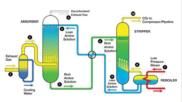
Post combustion carbon capture involves mixing the plant flue gas with a specialized chemical, typically an amine-based solvent, which has an engineered affinity to CO2 . The CO2-rich solvent is then processed (via heating) to separate out the CO2, which is compressed for transport (Figure 1).
The compressed CO2 is delivered by dedicated pipeline to a geologic formation deep underground for permanent sequestration. Or it may be used as feedstock for an industrial manufacturing process, thus completing the carbon capture, utilization sequence.
A variety of technologies exist today to separate CO2 from the exhaust of coal-fired power plants, with CO2 concentrations on the order of 10-12% by volume. Solvent-based carbon capture, for instance, has been demonstrated at scale and in operation at the Boundary Dam (Canada) and PetraNova (Texas) projects.
This same type of technology is being considered for many NGCC plants, both as retrofit and new builds under development, with exhaust gas CO2 concentration only, on the order of 3-5% by volume.
To date, however, the process has only been applied commercially to a ~15% slipstream of flue gas from a 300MW combined cycle cogeneration plant (ca. 1990-2004, Bellingham, Massachusetts ) but has yet to be deployed at full scale.
Carbon capture impacts
Solvent based carbon capture processes are commercially available to separate low concentrations (~3-5% by volume) of CO2 from the gas turbine exhaust .
However, the simple bolt-on addition of such a chemical plant to the exhaust end of a combined cycle plant has several economic and operational drawbacks:
- Capital cost of the carbon capture plant is typically at least as high as that of the combined cycle plant.
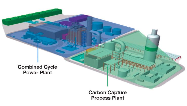
- Land required for addition of carbon capture doubles the footprint of the power plant facility (Figure 2).
- Net efficiency of the power plant can drop by over 8% points to account for the substantial energy (kWh) penalty associated with CO2 separation and compression.
- Steam required for CO2 separation generated using an auxiliary boiler imposes additional fuel cost and CO2 emissions. Using extraction steam reduces steam turbine power output.
- Cost of electricity generated will increase by at least 65% to achieve over 90% carbon capture.
Further, the CO2 capture process, like any chemical plant, favors steady state operation . At times, this may conflict with the now typical dynamic operation of a modern combined cycle plant – with multiple startups and ramps – when dispatched for grid backup of intermittent renewable energy.
Read more: "Carbon Capture Market About to Explode"
Benefits of system integration
Rather than the simple add-on approach, better integration of combined cycle and carbon capture plants can reduce these impacts significantly. Major opportunities for system integration include (Figure 3):

1. Exhaust gas recirculation: Recirculating a portion of the HRSG exhaust flue gas back to the gas turbine inlet has the effect of increasing the CO2 concentration in the flue gas going to the carbon capture unit . This reduces the size of the CO2 absorber required for a desired level of CO2 removal .
EGR can also result in other benefits including: a) reduced CCS process steam usage; b) reduced solvent oxidation and makeup due to lower O2 concentration in flue gas; and, c) reduced total mass emissions of NOx, SOx and particulates by up to 25% or more .
2. Steam integration: Using steam generated in the combined cycle for process heat, instead of installing a dedicated auxiliary boiler, results in lower CAPEX and lower OPEX. It also eliminates emissions associated with burning fuel in the boiler. About 15% reduction in CCS cost is expected compared to the separate boiler scenario .
3. Higher back pressure. The gas turbine and heat recovery steam generator are engineered to handle the back pressure from the CO2 absorber. So it is technically possible to eliminate the stand-alone blower typically used to drive the exhaust gas through the absorber tower. This simplified plant configuration improves overall reliability of the integrated system.
4. Integrated controls: GE Vernova has developed the ability to control the combined NGCC and CCS plant through use of advanced integrated controls.
These incorporate advanced controls for EGR and steam extraction, as well as protections . Also featured are feed-forward algorithms such that the NGCC and CCS can work tightly coupled through the many transients that combined cycle plants regularly experience.
Combustion system considerations
GE Vernova has conducted extensive development work to offer EGR capability with the company’s gas turbines. Analytical and test experience indicates that maximum EGR flue gas flow is limited by the gas turbine combustor operability and secondary gas turbine component durability considerations over the life of the plant.
Since oxygen levels in the combustion air is reduced as EGR flow is increased, care must be taken not exceed these limits. If oxygen levels drop too low, the combustor will generate elevated combustion dynamics (pressure fluctuations) leading to flame instability and risk of flame separation and blow-out. In addition to EGR limitations based on stable flame operation, the maximum allowable EGR flue gas flow is also affected by the fuel composition (e .g., sulfur content) and the level of flue gas cleanup done in the EGR loop.
Excessive fuel contaminants with insufficient EGR flue gas cleanup will adversely impact gas turbine component life. There is similar risk of deterioration of hot-section thermal barrier coatings due to carry-over of particulates in recirculated flue gas.
All of these risks to combustor performance and gas turbine parts life must be considered and managed when offering EGR for a particular gas turbine design. GE Vernova recently demonstrated commercially available EGR-capable combustors for F- and HA-Class gas turbines at its combustion test facilities in Greenville, South Carolina.
Exhaust Gas Recirculation: How it works
The EGR system comprises several components (refer to numbered control points on Figure 4):

1. Flue gas dampers to control EGR flow and providing isolation when EGR system is OFF .
2. EGR purge provisions to purge any combustible gasses before EGR system startup .
3. EGR flue gas direct contact cooler (DCC); used to reduce EGR flue gas temperature to minimize the impact on gas turbine performance . The DCC includes enhanced flue gas cleanup to reduce SOx, particulate matter, and NOx .
4. EGR flue gas blower; used to drive the EGR flue gas to the gas turbine inlet and overcome EGR flow system pressure drops.
5. Ducting; used to return the recycled flue gas from the outlet to the inlet of the gas turbine . Due to the volume of flue gas, and required low pressure drop, significant attention must be given to minimizing the length and number of turns.
6. EGR flue gas mixer used to mix the EGR return flue gas with the fresh air entering via the gas turbine filter house. The design objective is a well- mixed flow with minimum pressure drop.
Gas turbine design considerations
EGR requires special consideration be given to several areas of gas turbine plant design to ensure safe, reliable, long-life operation. Key areas involved:
- Combustor: must have a flexible hardware configuration to reliably operate with elevated levels of combustor inlet CO2 and reduced O2 levels .
Both the GE Vernova DLN 2 .6+ Flex (7F gas turbine) and DLN 2 .6 (7HA/9HA gas turbines) dry low NOx combustors have been extensively tested using commercial grade combustors confirming substantial EGR capability.
- Inlet filtration: must use E12 level water-tight filtration to minimize chloride levels in the gas turbine compressor. Requires high efficiency particulate air (HEPA) filters able to block over 99 .5% of the most penetrating particle size (MPPS) blocking waterborne salt that would otherwise introduce air- borne chlorides .
- Metal surfaces: protective compressor casing coatings and corrosion sensors
NGCC transient considerations
Regarding NGCC plant start-up transients, EGR is expected to typically be engaged as soon as the gas turbine meets the minimum emissions compliance level (MECL) of operation. The EGR system does not have to be operational for the carbon capture unit to work. However, if the CCS plant is engineered to minimize CAPEX, operating without EGR will decrease capture rate when the NGCC operates at full power output .
At part-load operation the EGR system will operate in such a way as to elevate the EGR flue gas outlet temperature which, in turn, can be used to raise the gas turbine inlet temperature. This serves to: 1) reduce inlet bleed heat requirement, and 2) enable gas turbine operation with wider-open inlet guide vanes . Both results substantially improve gas turbine and combined cycle part-load efficiency.
Study confirms expected benefits
When EGR is applied to the NGCC plant design, several key benefits transfer directly to the design and performance of the carbon capture unit. The extent of these benefits, however, will vary from site-to-site .
For that reason, the reported Southern Company’s subsidiary Alabama Power’s Plant Barry FEED study results, below, exemplify specific benefits in the case of that one location:
- Smaller CO2 absorber. Although containing the same amount of CO2 (lb/hr), with EGR the flue gas entering the absorber column is at higher concentration, carrying with it lower amounts of H2O, N2, O2 and Ar .
Study results confirmed that the higher concentration and reduced flue gas flow volume dramatically reduces required absorber cross-sectional area (by almost half), lowering carbon capture plant costs and footprint; absorber tower height is slightly reduced as well.
In the case of the Plant Barry retrofit, the number of towers per carbon capture train (one train per gas turbine) was reduced from two to one.
Overall, the total cost of the capture unit with EGR was found to be more than 6% below that of the case without EGR.
- Lower plant emissions: reduction in plant emissions (lb/hr and ppm levels)
Study results indicate plant emissions of NOx, PM, and CO are reduced by 40% with EGR.
- Lower O2 concentration: reduces rate of oxidation of the solvent (up to 15%) and reduced levels of solvent makeup .
Study results confirm indicate EGR reduced the oxygen level in the NGCC flue gas (fed to the carbon capture plant) from 12.1% to 7.1% by volume.
- Reduced steam demand: Increased CO2 concentration in the flue gas enables the carbon capture plant to operate with an elevated (richer) CO2 solvent, reducing heat required to separate the CO2 from the solvent.
Study results confirmed that adding EGR increased CO2 concentration in the flue gas from 4.0 to 6.7% (vol), reducing extraction steam required for the reboiler. This increased plant net power output by 7.5MW – from 543.9MW without EGR to 551.4MW with EGR. Heat rate improved by 0.5% with EGR.
- Other benefits: increased CO2 concentration in the flue gas can drive overall CO2 capture efficiency up by 1 .5 to 2% for a baseline design of 95% carbon capture . Although increased CO2 capture may require slightly larger CO2 compressors, there will still be reduced absorber exhaust emissions, reduced solvent makeup, and increased combined cycle power and efficiency.
Summing it up
As confirmed by the Plant Barry retrofit FEED study, EGR is a key technology to help overcome the various negative impacts of conventional add-on carbon capture systems and contribute significantly to faster adoption of CCS on NGCC plants. In the US, this will be bolstered by continued government policy support and financial incentives such as those available under the Inflation Reduction Act of 2022.
Meanwhile, with or without carbon capture, gas-turbine based power generation will continue to play a vital role in the global energy transition. This reality is being widely demonstrated around the world, both as a carbon-lowering replacement of coal-fired generation and as the key element of critical backup power and grid protection made necessary by the growing contribution of intermittent wind and solar renewable energy.
DOE Acknowledgement: “This material is based upon work supported by the Department of Energy under Award Number DE-FE0032131